Tag: Tolerance Analysis

  • ZAMAK 3 Pearl Chrome Die Casting 8D Case Study: Assembly Step Interference from Local Excess Material

    8D Case Study / Assembly Quality

    ZAMAK 3 Pearl Chrome Die Casting 8D Case Study: Assembly Step Interference from Local Excess Material

    A sanitized 8D case for a ZAMAK 3 die cast and hexavalent pearl chrome plated part, showing how a suspected dimensional issue was traced to local excess material, mold erosion and fitting interference with the mating plastic part.

    XSD Precision2026-07-10

    Sanitized Case Scope

    ItemSanitized Engineering Record
    Product typeZAMAK 3 zinc alloy die cast decorative keychain/key-holder component assembled with a mating plastic part.
    Surface finishHexavalent pearl chrome plating after degating, deburring, drilling and tapping, grinding and polishing.
    Problem signalAssembly step protrusion could be felt by hand after fitting; the initial concern was whether two key dimensions were related to the step issue.
    Confidentiality noteCustomer name, supplier name, company name, personnel names and product part numbers have been removed from this case study.

    8D Investigation Route

    Customer-side NG sortingPlastic-part refitting checkDimensional sample reviewLocal interference observationMold condition inspectionMold repair and 50-piece verificationProfile-gauge control after polishingDrawing tolerance review

    Containment and Sorting Evidence

    ActionResult
    Customer-side sorted NG partsAfter replacing and refitting the mating plastic part, only a small number still showed step protrusion, indicating the issue was not explained by metal-part dimensions alone.
    Returned batch refitting inspectionA returned batch was checked by actual plastic-part fitting; conforming pieces were released after fitting confirmation.
    Internal stock inspectionIn-process inventory was checked by actual fitting and confirmed acceptable.
    Dimensional sampleA 200-piece sample from acceptable fitting parts showed that some dimensions exceeded current drawing limits but still assembled without step protrusion.

    Root Cause Analysis

    • The suspected dimensions did not show a strong direct relationship with the assembly step complaint. Some parts above the current drawing upper limits still fitted acceptably.
    • Parts close to the lower side of one dimension were more likely to show fitting step risk, so simply forcing the dimension toward the lower tolerance side was not recommended.
    • For the remaining step NG parts, local excess material was found at the interference area. After filing the excess material, the same parts were refitted and the step disappeared.
    • Upstream checking found that rough castings had different levels of local excess material at the same area. Polishing did not remove it because the location was not part of the normal appearance-polishing surface.
    • Mold inspection found erosion/wear at the corresponding mold position. This created local lift or bulge at the die cast arc corner, causing interference with the mating plastic part.

    True Cause Statement

    The assembly step issue was primarily caused by local excess material from mold erosion/wear at a non-polished arc area. The raised area interfered with the mating plastic component during fitting. The dimensional out-of-spec discussion was a useful investigation input, but it was not the direct root cause of the step protrusion.

    Verification After Correction

    Verification itemOutcome
    Local excess material removalThe originally NG parts were filed at the interference area, then refitted; the step protrusion disappeared.
    Mold repairThe corresponding mold area was repaired and polished to remove the erosion-related surface condition.
    Post-repair trial50 pieces were verified after mold correction and fitting result was acceptable.
    Dimension reviewPost-repair fitting remained acceptable across a wider observed dimension range, supporting the conclusion that assembly stack-up and local interference control were more important than the original two dimensions alone.

    Permanent Corrective Actions

    • Repair and maintain the eroded mold area so the rough casting no longer forms a local lifted arc or excess material.
    • Add a profile fixture or contour gauge after polishing to check the non-obvious interference area before final assembly.
    • Use actual fitting confirmation for this assembly interface, especially when the mating plastic part may have shrinkage variation.
    • Review plastic-part shrinkage stability together with the metal-part tolerance, instead of judging the problem from the metal part alone.
    • Review drawing tolerances for the two discussed dimensions only after dimensional distribution, fitting evidence and customer acceptance criteria are aligned.
    • Update inspection focus so that future checks cover both previous functional issues and new corner/step protrusion risks.

    Case Takeaway

    For pearl chrome plated ZAMAK 3 die cast assemblies, a visible or touchable step can come from a small local interference area rather than from the most obvious drawing dimensions. A reliable 8D route should combine dimensional data, actual fitting, mating plastic shrinkage review, mold wear inspection and fixture-based contour control.

    Need die casting assembly interference review?

    Send drawings, samples, fitting criteria, plating requirements and mating-part information. XSD can support dimensional review, mold-risk analysis and corrective-action planning.

    Send Inquiry

    8D 案例学习 / 装配质量

    ZAMAK 3 珍珠铬压铸件 8D 案例:局部多料导致装配台阶干涉

    本脱敏 8D 案例针对 ZAMAK 3 锌合金压铸并电镀六价珍珠铬的产品,说明如何从尺寸争议追溯到局部多料、模具冲蚀以及与塑胶件装配干涉的真实风险点。

    XSD Precision2026-07-10

    脱敏案例范围

    项目脱敏工程记录
    产品类型ZAMAK 3 锌合金压铸装饰类钥匙扣/钥匙挂件,与塑胶件配合装配。
    表面处理压铸、去水口、去毛刺、钻孔攻牙、打磨抛光后,进行六价珍珠铬电镀。
    问题信号装配后局部台阶凸出,用手触摸有刮手感;初期关注点集中在两个关键尺寸是否与台阶问题有关。
    脱敏说明本文已删除客户名称、供应商名称、公司名称、人员姓名和产品料号,仅保留工程分析逻辑。

    8D 排查路线

    客户端不良挑选更换塑胶件实配尺寸样本复测观察局部干涉点检查模具状态修模后 50 件验证抛光后仿形治具检测图纸公差评审

    临时围堵与挑选证据

    动作结果
    客户侧挑出不良品更换配合塑胶件并重新实配后,仅少量产品仍出现台阶,说明问题不能只用金属件两个尺寸解释。
    退回批次实配检验退回批次使用塑胶件进行实际适配检测,适配合格品按结果放行。
    内部库存检查在制库存通过实配方式全检确认合格。
    尺寸样本分析对 200 件适配 OK 的产品测量后发现,部分尺寸虽超出当前图纸上限,但实际装配无台阶。

    原因分析

    • 最初关注的两个尺寸与台阶刮手问题没有表现出强直接关联;部分超出当前图纸上限的产品仍可实配 OK。
    • 某一尺寸靠近下偏差时反而更容易出现台阶风险,因此不建议简单要求该尺寸尽量走下公差。
    • 对仍然不良的样件仔细观察后,发现局部存在多料并与塑胶件干涉;将多料位置修挫后重新实配,台阶消失。
    • 继续往前排查,发现毛坯件同一位置存在不同程度多料;该位置不属于正常外观打磨抛光区域,因此抛光无法自动修复。
    • 检查模具后发现,对应位置存在冲蚀/磨损,导致压铸件圆弧角局部翘起或形成轻微凸包,最终与塑胶件配合时形成断差台阶。

    真因结论

    本案例中,台阶刮手的主要原因是模具对应位置冲蚀/磨损,引起非抛光圆弧区域局部多料或翘起,装配时与塑胶件发生干涉。尺寸超差是重要排查线索,但不是造成台阶凸出的直接真因。

    改善验证

    验证项目结果
    局部多料修挫将原不良样件干涉部位修挫后重新实配,台阶消失,实配 OK。
    模具维修对模具冲蚀位置进行维修和省模,使对应表面恢复光顺,避免毛坯局部翘起。
    修模后试产修模后验证 50 件,实配结果合格。
    尺寸复核修模后在更宽的尺寸分布范围内仍可实配 OK,进一步说明装配尺寸链和局部干涉控制比单独两个尺寸更关键。

    永久纠正措施

    • 对模具冲蚀/磨损区域进行维修维护,避免毛坯在圆弧角产生局部翘起或多料。
    • 抛光后增加仿形治具或轮廓检具,专门检查容易被外观检验忽略的干涉区域。
    • 该装配界面采用实配确认,尤其在配合塑胶件存在缩水波动时,不只依赖单一金属件尺寸判定。
    • 同步关注塑胶件缩水稳定性,把塑胶件尺寸、金属件尺寸和台阶外观一起纳入装配尺寸链管理。
    • 对两个争议尺寸进行图纸公差评审,但应以尺寸分布、实配证据和客户允收标准一致为前提。
    • 更新检验关注点,避免只确认前期已发生过的问题,而忽略角部凸出、台阶不平等新的装配外观风险。

    案例启示

    ZAMAK 3 珍珠铬压铸装配件出现台阶或刮手感时,不能只盯住图纸上最显眼的几个尺寸。可靠的 8D 路线应同时结合尺寸数据、实配结果、塑胶件缩水、模具磨损状态和仿形治具检测,才能避免误判真因。

    需要压铸装配干涉问题评审?

    请提供图纸、样件、适配标准、电镀要求和配合件信息。XSD 可协助进行尺寸评审、模具风险分析和纠正措施规划。
    发送询盘
  • ZAMAK 3 Pearl Chrome Die Casting Case Study: Assembly Step Dimension Analysis and Tolerance Review

    Die Casting Case Study / Dimension Control

    ZAMAK 3 Pearl Chrome Die Casting Case Study: Assembly Step Dimension Analysis and Tolerance Review

    A ZAMAK 3 die casting and hexavalent pearl chrome plating case combining production fitting inspection, dimensional sampling and a 148-piece three-level DOE to evaluate how 37.50, 37.55 and 37.60 dimension settings relate to loose-fit risk.

    XSD Precision2026-07-10

    Case Background

    ItemEngineering Record
    Material and processZAMAK 3 zinc alloy die casting with hexavalent pearl chrome plating.
    Production routeDie casting, degating, deburring, drilling and tapping, grinding and polishing, pearl chrome plating, threaded insert assembly, inspection and packing.
    Quality concernDimensional concern suspected to cause assembly appearance issues, especially step protrusion after fitting with the mating plastic part.
    In-process lot3500 pcs were checked by fitting inspection; after fitting, the assembly step protrusion was confirmed acceptable.
    Dimensional sample200 pcs were randomly selected from this batch for measurement of two key dimensions.

    Inspection Logic

    In-process fitting check: 3500 pcsRandom dimensional sample: 200 pcsMeasure two key dimensionsCompare against current drawing limitsCheck relationship with assembly step resultReview tolerance and mating plastic shrinkage

    Measurement Summary

    DimensionCurrent specificationCurrent lower limitCurrent upper limitSample minimumSample maximumResult
    14.3±0.114.20 to 14.4014.2014.4014.2614.75Exceeds upper specification limit.
    37.34+0.15/-0.137.24 to 37.4937.2437.4937.3537.65Exceeds upper specification limit.

    Assembly Result

    Although both measured dimensions exceed the current drawing upper limits under the present manufacturing route, the fitting inspection showed that the assembly step protrusion was acceptable after adaptation. Based on this batch evidence, the step appearance result did not show a significant correlation with these two measured dimensions alone. This finding applies to step protrusion appearance in that production batch and should not be generalized to the separate loose-fit response evaluated in the follow-up DOE.

    Engineering Analysis

    • The two metal-part dimensions are out of the current drawing limits, so the drawing and process capability cannot be judged only by nominal conformance.
    • The accepted assembly step result indicates that the actual appearance risk is likely controlled by the full assembly stack-up, not by either dimension alone.
    • Based on the dimensional distribution and the fitting result, the mating plastic part should be checked for shrinkage, because plastic shrinkage may shift the actual assembly relationship.
    • A metal-part-only rejection rule could create unnecessary sorting if the final assembly function and appearance are still acceptable.

    Follow-up DOE: 37.50, 37.55 and 37.60

    A follow-up full inspection compared three nominal dimension levels against loose-fit results. Material defects and plating defects were recorded as separate dispositions so that assembly-fit behavior could be evaluated on both the total-inspection basis and the effective-fit basis.

    Full inspection record

    Dimension levelFit OKLoose fitMaterial defectPlating defectTotalLoose / total
    37.502130415653.57%
    37.5529256424.76%
    37.602417185034.00%

    Effective fit comparison

    Because material and plating defects do not provide an independent fit judgment, the primary comparison uses only parts classified as fit OK or loose fit.

    Dimension levelFit OKLoose fitEffective fit sampleLoose-fit rate
    37.5021305158.82%
    37.55292316.45%
    37.6024174141.46%

    Statistical result: Pearson chi-square = 22.13, p = 0.0000156 and Cramer’s V = 0.424. Under these sampled conditions, dimension level and loose-fit result show a statistically significant, medium-to-strong association.

    DOE Interpretation and Decision Boundary

    • 37.55 produced the lowest effective loose-fit rate at 6.45%, compared with 58.82% at 37.50 and 41.46% at 37.60.
    • The odds of a loose fit were approximately 20.7 times higher at 37.50 than at 37.55, and approximately 10.3 times higher at 37.60 than at 37.55.
    • The difference between 37.50 and 37.60 is not conclusive on the effective-fit basis because its 95% confidence interval includes 1.
    • The response is non-linear: the middle level performed best, so the data do not support a simple rule that increasing or decreasing the dimension continuously increases looseness.
    • Combined material and plating defect rates also varied by group: 8.93% at 37.50, 26.19% at 37.55 and 18.00% at 37.60. This variation indicates possible batch, cavity, polishing or plating confounding.

    Engineering conclusion: the current data support an association between the tested dimension levels and loose-fit outcome, but they do not prove that dimension alone caused the difference. The 37.55 level is the best candidate among the three tested settings and should be treated as a validation center point, not yet as a released production tolerance.

    Recommended Confirmation DOE

    Add 37.525 and 37.575 center-adjacent levelsCollect at least 50 effective fit results per levelRandomize run order and block by production lotRecord cavity, casting, polishing and plating batchMeasure actual continuous dimension, not nominal level onlyUse one mating-part lot and a defined fit gauge

    Analyze the confirmation run with logistic regression including linear and quadratic dimension terms, with lot or cavity used as blocking factors. This will test whether the apparent middle optimum is repeatable and separate dimension influence from process variation.

    Tolerance Review Direction

    DimensionCurrent toleranceProposed review toleranceEngineering note
    14.314.3±0.114.3+0.25/-0.1This raises the upper limit to 14.55, but the observed sample maximum is 14.75. Outliers and full distribution still require review.
    37.3437.34+0.15/-0.137.34+0.25/-0.1This raises the upper limit to 37.59, but the observed sample maximum is 37.65. Additional validation is needed before formal drawing release.

    The proposed tolerance change should be treated as a drawing-review direction, not as a final approval by itself. Before release, XSD recommends confirming plastic-part dimensions, assembly stack-up, step protrusion gauge criteria, and Cpk/Ppk or batch-distribution evidence.

    Improvement Actions

    • Measure the mating plastic part and confirm whether shrinkage is present across different cavities, batches or suppliers.
    • Create an assembly stack-up record connecting metal dimensions, plastic dimensions and accepted step protrusion results.
    • Use a dedicated fitting gauge or visual limit sample for the step protrusion acceptance decision.
    • Separate true dimensional outliers from tolerance limits that may be too narrow for the functional assembly requirement.
    • Only revise the drawing tolerance after sample distribution, assembly validation and customer acceptance criteria are aligned.

    Need die casting dimension and assembly stack-up review?

    Send drawings, measurement samples, mating-part data and assembly acceptance criteria. XSD can help separate true dimensional risk from functional assembly tolerance.

    Send Inquiry

    压铸案例学习 / 尺寸控制

    ZAMAK 3 珍珠铬压铸件案例:装配台阶尺寸分析与公差评审

    本案例针对ZAMAK 3锌合金压铸并电镀六价珍珠铬的产品,结合在制适配检测、尺寸抽样和148件三水平DOE,分析37.50、37.55与37.60尺寸档位对实配松风险的影响。

    XSD Precision2026-07-10

    案例背景

    项目工程记录
    材料与工艺ZAMAK 3 锌合金压铸,电镀六价珍珠铬。
    生产路线压铸、去水口、去毛刺、钻孔攻牙、打磨抛光、电镀珍珠铬、组装螺纹牙套、检验、包装。
    质量关注点因尺寸问题怀疑导致装配外观质量问题,重点关注与塑胶件适配后的台阶凸出状态。
    在制批量对在制 3500 件进行适配检测,经适配后确认台阶凸出合格。
    尺寸样本从本批中随机抽查 200 件组成样本,对两个关键尺寸进行测量和分析。

    检测逻辑

    在制适配检测:3500 件随机尺寸样本:200 件测量两个关键尺寸对比当前图纸规格判断与装配台阶结果的关系评审公差与塑胶件缩水

    测量数据摘要

    尺寸当前规格当前下限当前上限样本最小值样本最大值判定
    14.3±0.114.20 至 14.4014.2014.4014.2614.75超出当前规格上限。
    37.34+0.15/-0.137.24 至 37.4937.2437.4937.3537.65超出当前规格上限。

    装配结果

    虽然按目前加工工艺,这两个尺寸均超出当前图纸规格上限,但本批产品经适配后,台阶凸出结果确认合格。基于本批适配证据,装配后台阶外观结果与这两个单独测量尺寸之间未表现出显著关联。该结论只适用于本批产品的台阶凸出外观,不能直接外推到追加DOE所评价的“实配松”响应。

    工程分析

    • 两个金属件尺寸确实超出当前图纸规格,因此不能只按名义规格直接判断工艺能力已经满足图纸。
    • 台阶适配结果合格,说明实际外观风险更可能由整套装配尺寸链共同决定,而不是由某一个金属件尺寸单独决定。
    • 根据尺寸分布和适配结果,建议重点复测与之配合的塑胶件,判断是否存在缩水导致的装配关系偏移。
    • 如果只按金属件当前图纸上限进行拒收,可能会产生不必要的挑选和返工,但如果直接放宽公差,也需要数据证据支撑。

    追加DOE:37.50、37.55与37.60尺寸档位

    追加全检试验比较三个名义尺寸档位与“实配松”的关系。素材不良和电镀不良分别记录,避免把不能独立完成实配判定的样品直接混入装配松紧分析。

    全检原始记录

    尺寸档位实配OK实配松素材不良电镀不良总数实配松/总数
    37.502130415653.57%
    37.5529256424.76%
    37.602417185034.00%

    有效实配口径

    素材和电镀不良不能提供独立的实配松紧判定,因此主分析只使用“实配OK”和“实配松”两类样品。

    尺寸档位实配OK实配松有效实配数实配松率
    37.5021305158.82%
    37.55292316.45%
    37.6024174141.46%

    统计结果:Pearson卡方值=22.13,p=0.0000156,Cramer’s V=0.424。在本次样品条件下,尺寸档位与实配松结果存在显著且中等偏强的关联。

    DOE解释与决策边界

    • 37.55的有效实配松率最低,为6.45%;37.50为58.82%,37.60为41.46%。
    • 37.50相对于37.55的松动几率约高20.7倍;37.60相对于37.55约高10.3倍。
    • 在有效实配口径下,37.50与37.60之间的差异尚不足以确认,其95%置信区间包含1。
    • 结果呈非线性,中间档位表现最好,不能解释为尺寸单纯增大或减小就会持续增加松动。
    • 三组素材与电镀综合不良率分别为8.93%、26.19%和18.00%,提示批次、模穴、抛光或电镀条件可能构成混杂因素。

    工程结论:现有数据支持测试尺寸档位与实配松结果有关联,但不能证明尺寸是造成差异的唯一原因。37.55是三个测试档位中的最佳候选,应作为下一轮验证中心点,暂不直接作为已批准的量产公差。

    下一轮确认DOE建议

    增加37.525和37.575两个中心邻近水平每个水平至少取得50件有效实配样品随机化试验顺序并按生产批次区组记录模穴、压铸、抛光和电镀批次记录实际连续尺寸,不只记录名义档位统一配合件批次并定义实配检具

    确认试验建议采用包含尺寸线性项和二次项的逻辑回归,并将批次或模穴作为区组因素,从而验证中间最优现象能否重复,并区分尺寸影响与制程波动。

    公差评审建议

    尺寸当前公差建议评审公差工程备注
    14.314.3±0.114.3+0.25/-0.1上限调整后为 14.55,但样本最大值为 14.75,仍需确认是否存在异常点或是否需要进一步评审尺寸链。
    37.3437.34+0.15/-0.137.34+0.25/-0.1上限调整后为 37.59,但样本最大值为 37.65,正式改图前仍需增加装配验证和分布分析。

    因此,14.3+0.25/-0.1 和 37.34+0.25/-0.1 更适合作为图纸公差优化的评审方向,而不是直接作为最终放行结论。正式变更前,建议补充塑胶件尺寸、装配尺寸链、台阶凸出限度样和 Cpk/Ppk 或批量分布证据。

    质量改进动作

    • 同步测量配合塑胶件,确认不同模穴、批次或供应商是否存在缩水差异。
    • 建立金属件尺寸、塑胶件尺寸与台阶凸出结果之间的装配尺寸链记录。
    • 针对台阶凸出建立专用适配检具或外观限度样,避免只靠单一尺寸判定。
    • 区分真实尺寸异常点与当前图纸公差偏窄两类问题,分别采取修模、挑选或改图措施。
    • 公差变更应在样本分布、装配验证和客户允收标准一致后再正式导入图纸。

    需要压铸尺寸与装配尺寸链评审?

    请提供图纸、测量样本、配合件数据和装配允收标准。XSD 可协助区分真实尺寸风险与功能装配公差边界。

    发送询盘
  • Zinc Alloy Die Casting Dimensional NG Assembly Failure Case Study

    Zinc Alloy Die Casting Dimensional NG Assembly Failure Case Study

    Quality Case / Zinc Alloy Die Casting Dimensional Control

    Zinc Alloy Die Casting Dimensional NG Assembly Failure Case Study

    This case shows a zinc alloy die casting dimensional NG issue where excessive raised height and step gap cause visible assembly mismatch. The defect affects cover fit, button feel, cosmetic gap and customer perception.

    XSD Precision2026-07-10Zinc Alloy Die CastingDimensional Control
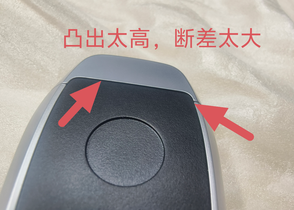
    Field defect photo: excessive raised height and step gap create visible assembly mismatch and fit risk.
    Field defect photo: excessive raised height and step gap create visible assembly mismatch and fit risk.
    The field photo shows visible step mismatch between the black top cover and the silver zinc alloy housing. This is usually not only a cosmetic problem. It is the result of the tolerance chain, die casting deformation, parting-line control, secondary machining or polishing reference and assembly fixture control.
    Dimensional NGRaised height, edge step or assembly datum out of tolerance
    Assembly FailurePoor cover fit, visible gap and abnormal button feel
    Production RiskRework, complaint, cosmetic rejection and yield loss

    Defect Symptom

    • The local zinc alloy housing surface is too high, so the black decorative cover cannot sit flat.
    • A visible step appears along the top or side edge after assembly.
    • The assembled gap becomes inconsistent and can be judged as cosmetic NG or assembly NG.
    • If the location is near a button or clip, it may also affect button travel, clip stress and cover lift.

    Likely Causes

    CauseInspection FocusTypical Symptom
    Die casting dimensional variationMold temperature, injection pressure, holding pressure, cooling time, shrinkage and warpageBatch drift or local raised height
    Mold parting surface or insert wearParting line, insert step, cavity damage and vent areaFixed-position step, burr or mismatch
    Unstable secondary-process datumCNC location, deburring, polishing, blasting or plating pretreatmentCosmetic surface dimension is enlarged or uneven
    Open assembly tolerance chainCover, glue area, clips, foam tape and housing datumIndividual parts pass, but assembly gap fails
    Gauge coverage gapGauge checks outline only, not raised height, step gap or assembly flatnessOutgoing inspection passes, final assembly fails

    Recommended Inspection Points

    • Raised feature height with height gauge, vision measurement or go/no-go gauge.
    • Assembly step gap with feeler gauge, step gauge or 3D scan.
    • Assembly surface flatness around cover seating, clip area and button support area.
    • Cavity traceability to confirm whether the defect concentrates in one cavity or insert.
    • Real assembly trial for each batch, not only individual part dimension inspection.
    • Touch-feel criterion for visible and touchable cosmetic edges.

    Corrective Actions

    • Measure the actual raised amount first instead of judging only from photos.
    • Build the tolerance chain of cover, zinc alloy housing, clip and glue area.
    • If the same position repeats, check mold insert, parting surface damage and local burr.
    • If the issue varies by batch, check die casting parameters, mold temperature and cooling rhythm.
    • If single parts pass but assembly fails, revise the assembly gauge or add final assembly sampling.
    • Before mass production, write key height, step gap and flatness into SIP, gauge drawing and outgoing criteria.

    Production Control Recommendation

    For automotive key housings, TPMS housings, decorative housings and visible cosmetic parts, dimensional control cannot rely only on individual drawing tolerance. The end customer sees the assembled gap, step and touch feel. XSD should evaluate single-part dimensions, assembly tolerance chain and cosmetic step criteria together.

    The key is not only where the part is raised. The key is connecting raised amount, step gap, assembly interference and cavity or process source, so the team can decide whether to correct the mold, tune the process, revise the gauge or modify the assembly tolerance chain.

    Need help reviewing zinc die casting dimensional NG or assembly step gap?

    Send product photos, 2D/3D drawings, measurement data, assembly photos and gauge requirements. XSD can help identify root cause and corrective route.

    Send Dimensional Data

    质量案例 / 锌合金压铸尺寸控制

    锌合金压铸尺寸 NG 导致装配故障案例:凸出过高与断差过大

    这类问题表面看是外观断差,实际会影响面壳贴合、按键手感、装配间隙和终端客户感知。锌合金压铸件如果凸台高度、分型面披锋或后加工基准没有控制好,就会在最终装配时集中暴露。

    XSD Precision2026-07-10Zinc Alloy Die CastingDimensional Control
    现场缺陷图:凸出过高、断差过大,装配后形成明显台阶和间隙风险。
    现场缺陷图:凸出过高、断差过大,装配后形成明显台阶和间隙风险。
    现场照片显示:黑色面壳与银色锌合金外壳之间出现明显凸出和断差。该问题通常不是单一外观问题,而是尺寸链、压铸变形、分型面处理、CNC/抛光基准和装配夹具共同作用后的结果。
    尺寸 NG凸台高度、边缘断差或装配面尺寸超差
    装配故障面壳贴合不平、间隙变大、按键手感异常
    量产风险返工、客诉、外观判退和良率损失

    缺陷现象

    • 银色锌合金壳体局部凸出太高,黑色装饰面壳无法自然贴平。
    • 左右边缘或顶部边缘形成明显断差,手摸有台阶感。
    • 装配后外观缝隙不一致,可能被判定为外观 NG 或装配 NG。
    • 如果该位置靠近按键或卡扣,还可能造成按键行程异常、卡扣受力和面壳翘起。

    可能原因

    原因类别检查方向典型表现
    压铸尺寸波动模温、射出压力、保压、冷却时间、缩水和翘曲同一模穴批量尺寸漂移,局部高度偏高
    模具分型面或镶件磨损分型面、镶件台阶、模仁压伤、排气位置边缘台阶、披锋、断差集中在固定位置
    后加工基准不稳定CNC 定位、去毛刺、抛光、喷砂或电镀前处理外观面尺寸被二次加工放大或不均匀
    装配尺寸链未闭合面壳、胶位、卡扣、泡棉、双面胶和壳体定位面单件尺寸勉强合格,但装配后间隙超差
    检具没有覆盖装配面只检外形长宽,没有检凸台高度、台阶差和装配面平面度出货检验通过,终端装配才暴露

    建议增加的检验项目

    • 凸台高度:用高度规、影像仪或专用通止规确认关键高度差。
    • 装配断差:用塞尺、台阶规或 3D 扫描确认面壳与壳体边缘差值。
    • 装配面平面度:重点检查贴合面、卡扣面和按键周边支撑面。
    • 模穴追溯:按模穴编号记录尺寸,判断是否集中在某一模穴或某一镶件。
    • 试装验证:每批抽样真实装配面壳,不只做单件尺寸检验。
    • 外观触感判定:对可触摸边缘设定手感断差标准,避免仅靠目视判断。

    改善动作

    • 先用 3D 或高度测量确认实际凸出量,不要只凭照片判断。
    • 把面壳、锌合金壳体、卡扣和胶位建立尺寸链,确认允许断差范围。
    • 如果固定位置重复发生,优先检查模具镶件、分型面压伤和局部披锋。
    • 如果批次间波动明显,优先检查压铸参数、模温和冷却节拍。
    • 如果压铸单件合格但装配 NG,需要修正装配检具或增加总成试装工序。
    • 量产前把关键高度、断差和平面度写入 SIP、检具图和出货判定标准。

    量产控制建议

    对汽车钥匙壳、TPMS 外壳、装饰壳和可视外观件来说,尺寸控制不能只看单件图纸公差。最终客户看到的是装配后的缝隙、断差和手感。因此,XSD 在锌合金压铸项目中应把单件尺寸、装配尺寸链和外观断差标准合在一起评估。

    重点不是“哪里凸出来了”,而是要把凸出量、断差、装配干涉和模穴/工序来源关联起来。只有这样才能判断是修模、调机、改检具,还是修改装配尺寸链。

    需要评估锌合金压铸尺寸 NG 或装配断差?

    发送产品图、2D/3D 图纸、尺寸实测数据、装配照片和检具要求,XSD 可以协助判断问题来源并整理改善路线。

    发送尺寸问题资料
  • Zinc Die Casting Small Hole Tolerance Control Case Study: 5.95mm vs 5.90mm

    Engineering Guide / Small Hole Tolerance

    Zinc Die Casting Small Hole Tolerance Control Case Study: 5.95mm vs 5.90mm

    Engineering judgement, mold-correction priorities and process checks for a 5.95mm vs 5.90mm two-cavity difference in 88T zinc die casting.

    XSD Precision2026-07-10Zinc Alloy Die Casting88T Small Part
    This case uses a two-cavity small-hole measurement difference to explain realistic tolerance control for small zinc alloy die castings. On an 88T die casting machine, a 0.05mm difference between two cavities is not unusually large, but it is already meaningful when the hole is a key assembly dimension.
    5.95mmSample size
    5.95mmCavity 1 casting
    5.90mmCavity 2 casting
    0.05mmCavity difference

    Tolerance Reality for Small Die Castings

    Material / Control LevelRealistic Production ToleranceEngineering Meaning
    Zinc alloy small partsAround ±0.05mm for ordinary stable productionRealistic for normal mass production when the mold, machine and measurement system are stable.
    Zinc alloy with good controlAround ±0.03mmRequires better mold precision, stable mold temperature and stricter measurement discipline.
    Zinc alloy high-precision targetWithin ±0.02mmDifficult. Usually requires high-precision mold inserts, stable thermal control, strict inspection, and sometimes post-machining or 100% sorting.
    Aluminum alloy small partsAround ±0.08-±0.15mm for ordinary stable productionAluminum die casting has greater shrinkage and thermal variation, so long-term ±0.03mm control is difficult.
    Zinc stable production
    ±0.05mm
    Zinc good control
    ±0.03mm
    High precision target
    ±0.02mm

    Case Measurement

    ItemMeasured ValueInterpretation
    Sample hole size5.95mmReference size for comparison.
    Cavity 1 raw casting5.95mmMatches the sample dimension.
    Cavity 2 raw casting5.90mm0.05mm smaller than cavity 1.
    Cavity difference0.05mmAcceptable for many 88T zinc die casting conditions, but worth correcting if this is a key assembly dimension.

    How to Judge the Cause

    1If cavity 1 stays at 5.95mm and cavity 2 stays at 5.90mm, first check cavity-size difference, gate or runner imbalance, and mold-temperature inconsistency.
    2If both cavities fluctuate up and down, first check injection parameters, mold-temperature fluctuation, cooling, venting and ejection deformation.
    3If cavity 2 is also lighter than cavity 1, the likely cause is insufficient filling or intensification pressure in cavity 2.

    Correction Priorities

    • Measure at least 30-50 pieces per cavity before cutting steel; separate data by cavity number.
    • If the difference is stable, correct cavity 2 insert size or shutoff surface rather than adjusting the whole process.
    • Check gate balance, runner pressure loss and local filling sequence if cavity 2 is both smaller and lighter.
    • Check mold temperature at both cavities because a local temperature difference can change shrinkage and final hole size.
    • Confirm measurement method, gauge repeatability and operator consistency before deciding mold correction amount.
    • If the hole is a critical assembly feature, reserve post-machining, reaming or 100% sorting as the control plan.

    Conclusion: for an 88T zinc die casting project, holding a 5.95mm small hole around ±0.05mm is realistic. If two cavities must be controlled within 0.02-0.03mm, the work should focus on cavity correction, runner balance and mold-temperature stability, not only machine parameter adjustment.

    Need help reviewing small-hole dimensional stability?

    Send drawings, cavity measurement data, part weight, die casting parameters and mold-temperature records. XSD can help decide whether to correct the cavity, balance the runner or adjust the process window.

    Send Dimension Data

    工程指南 / 小孔尺寸控制

    锌合金压铸小孔尺寸控制案例:5.95mm 与 5.90mm 两穴差异

    88T 锌合金压铸中 5.95mm 与 5.90mm 两穴差异的工程判断、修模优先级和工艺排查方法。

    XSD Precision2026-07-10Zinc Alloy Die Casting88T Small Part
    这个案例用一个两穴小孔尺寸差来说明锌合金小件压铸的真实公差控制。对于 88T 压铸机来说,两穴差 0.05mm 不算异常大;但如果这个孔是关键装配尺寸,0.05mm 已经值得修模或调整工艺。
    5.95mm样品尺寸
    5.95mm1 号穴素材
    5.90mm2 号穴素材
    0.05mm两穴差异

    小件压铸公差现实

    材料 / 控制水平现实量产公差工程含义
    锌合金小件普通稳定量产约 ±0.05mm模具、机器和测量系统稳定时,这是比较现实的量产水平。
    锌合金控制较好约 ±0.03mm需要更好的模具精度、稳定模温和严格测量管理。
    锌合金高精度目标控制在 ±0.02mm 以内难度较高,通常需要高精密模具、稳定热控制、严格检测,甚至后加工或全检分选。
    铝合金小件普通稳定量产约 ±0.08-±0.15mm铝合金压铸收缩和热波动更大,长期稳定 ±0.03mm 很难。
    锌合金普通稳定量产
    ±0.05mm
    锌合金控制较好
    ±0.03mm
    目标高精度控制
    ±0.02mm

    本案例测量数据

    项目测量值判断
    样品孔尺寸5.95mm作为对比基准。
    1 号穴素材5.95mm与样品尺寸一致。
    2 号穴素材5.90mm比 1 号穴小 0.05mm。
    两穴差异0.05mm对 88T 锌合金压铸不算异常大;但如果是关键装配孔,已经值得修模或调整工艺。

    原因判断方法

    1如果 1 号穴稳定 5.95、2 号穴稳定 5.90,优先判断为模穴尺寸差、浇口/流道不平衡或模温不一致。
    2如果两个穴尺寸都上下波动,优先看压射参数、模温波动、冷却、排气和顶出变形。
    3如果 2 号穴重量也比 1 号穴轻,多半是 2 号穴充填或补压不足。

    修正优先级

    • 修模前至少按穴号分别测量 30-50 件,不能把两个穴的数据混在一起看。
    • 如果差异稳定,优先修正 2 号穴镶件尺寸或相关封胶面,而不是整体调工艺。
    • 如果 2 号穴尺寸更小且重量更轻,应检查浇口平衡、流道压损和局部充填顺序。
    • 检查两个穴的模温差异,因为局部模温不同会改变收缩和最终孔尺寸。
    • 修模前确认测量方法、检具重复性和操作员一致性,避免把测量误差当成模具误差。
    • 如果该孔是关键装配尺寸,应预留后加工、铰孔或全检分选作为控制方案。

    结论:88T 力劲机做 5.95mm 这种锌合金小孔,稳定做到 ±0.05mm 是现实的;如果两穴差要控制到 0.02-0.03mm,需要重点修正模穴、流道平衡和模温,而不是只靠调机参数。

    需要评估压铸小孔尺寸稳定性?

    发送图纸、穴号测量数据、产品重量、压铸参数和模温记录,XSD 可以协助判断该修模、调流道还是调整工艺窗口。

    发送尺寸数据