Case Study / Mold Structure Optimization
Zinc Alloy Die Casting Snap-Fit Drag Mark Mold Optimization Case Study
A new zinc alloy die casting mold developed snap-fit drag marks after about 500 pieces, corrected through insert, draft, radius, polishing, venting and ejection-balance optimization.
Visual Evidence
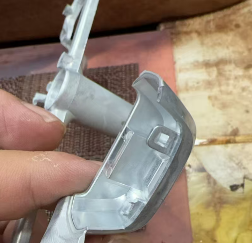
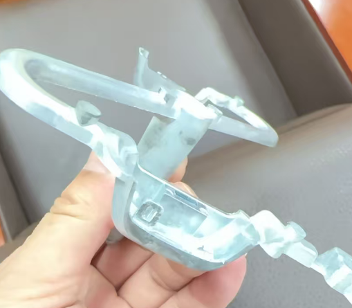
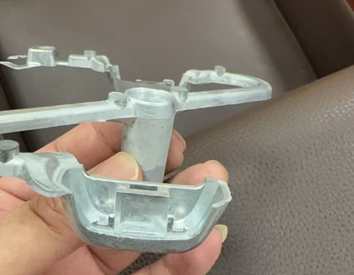
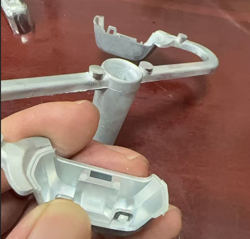
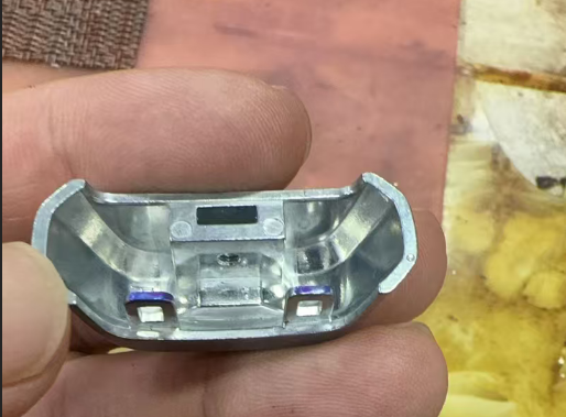
The photos show a thin snap-fit pocket, internal wall features and local marks around the buckle position. The problem should be reviewed as a mold-release and tooling-structure issue.
Engineering Diagnosis
| Observation | Likely Structural Cause | Verification Method |
|---|---|---|
| Drag mark appears after around 500pcs | Local release resistance accumulates after mold temperature stabilizes and zinc adhesion starts. | Check whether the first 100pcs are acceptable but later pieces show progressive sticking. |
| Snap-fit pocket has sharp transition and limited release space | Negative draft, small radius or metal-lock tendency around the snap-fit wall. | Blue-check the insert and inspect the exact contact line on the core. |
| Mark is concentrated near snap-fit / inner wall | Ejection force is unbalanced and the part rotates or rubs during release. | Review ejector position, push balance and part deformation after ejection. |
| New mold, early production issue | Local insert surface, polishing direction, nitriding or venting may be insufficient. | Inspect insert surface roughness, coating hardness, vent depth and trapped gas around the pocket. |
Mold Structure Optimization
| Optimization Item | Recommended Action | Purpose |
|---|---|---|
| Replaceable snap-fit insert | Separate the snap-fit area into an independent insert with clear shutoff, easy polishing and easy replacement. | Avoid scrapping or welding a large core when the snap-fit wears or sticks. |
| Draft correction | Add release draft on the snap-fit side wall. Use 1.5-3 degrees where function allows, and keep a controlled minimum on constrained surfaces. | Reduce hard pulling and prevent repeated drag marks. |
| Radius and edge relief | Increase local radius such as R0.2-R0.5 and remove sharp metal-lock edges around the pocket. | Lower release friction and reduce zinc tearing. |
| Slider or lifter review | If the buckle forms a real undercut, do not rely on hard release. Use a slider, lifter or revised parting strategy. | Release the undercut along its true movement direction. |
| Polishing and surface treatment | Polish along the release direction and consider nitriding, coating or higher-hardness insert steel for the local feature. | Reduce zinc alloy adhesion on a high-friction feature. |
| Ejection balance | Add or adjust ejector support near the snap-fit area if the part tilts during release. | Prevent the part from rubbing one side of the insert during ejection. |
| Local venting and overflow | Add micro venting or overflow near trapped-air and high-temperature points if marks connect with gas or carbon residue. | Improve local filling and reduce hot sticking conditions. |
Validation Standard
- Run a controlled re-trial after insert correction, not only a short machine start-up check.
- Use at least 500pcs as the first validation point because the original issue appeared at that level.
- If possible, continue to 1000pcs and inspect the same snap-fit insert contact line.
- Track drag mark, burr, snap-fit deformation, surface tear and ejection whitening or stress marks.
For zinc alloy die casting snap-fit structures, the safest correction is to solve the release path in the mold structure. Process adjustment can help, but it cannot reliably compensate for a real undercut or insufficient release angle.
Need help reviewing snap-fit drag marks in a die casting mold?
Send part photos, tooling structure, drag-mark location and trial quantity. XSD can help identify whether the issue is process, insert or mold-release structure.
Send Mold Issue案例学习 / 模具结构优化
锌合金压铸新模扣位拉模的模具结构优化案例
锌合金压铸新模生产约 500pcs 后扣位发生拉模,通过扣位镶件、拔模角、圆角、抛光排气和顶出平衡进行结构整改。
现场图片证据
图片显示扣位位置较薄,靠近内腔侧壁,局部存在窗口、台阶和内侧释放面。这个问题应按模具脱模路径和模具结构问题处理,而不是只靠喷脱模剂或降低模温。
工程诊断
| 现象 | 可能的结构原因 | 验证方法 |
|---|---|---|
| 约 500pcs 后出现拉模 | 模温稳定后局部粘锌、摩擦和脱模阻力累积,早期短时间试模不容易暴露。 | 对比前 100pcs 和后续批次,确认拉模是否逐步加重。 |
| 扣位口部和内壁有明显拉伤 | 扣位侧壁拔模角不足、尖角锁模、局部倒扣或释放方向不顺。 | 用蓝油检查镶件接触线,确认具体刮擦面。 |
| 拉模集中在扣位和内腔侧壁附近 | 顶出不平衡,产品脱模时发生偏摆,一侧与型芯或镶件摩擦。 | 复核顶针位置、顶出顺序和脱模后产品是否变形。 |
| 新模早期出现问题 | 局部镶件抛光方向、硬度、氮化/镀层、排气或溢流不足。 | 检查扣位镶件粗糙度、硬度、排气深度和高温困气位置。 |
模具结构优化方案
| 优化项目 | 建议动作 | 解决目的 |
|---|---|---|
| 扣位做独立可换镶件 | 将扣位区域拆成独立镶件,保证分型清晰、方便抛光、方便后续更换。 | 避免扣位磨损或粘模后需要大面积烧焊、改整块型芯。 |
| 修正拔模角 | 扣位释放面增加拔模角,功能允许处建议 1.5-3 度,受限制面也要保留受控最小拔模角。 | 减少硬拉,防止连续生产后反复拉伤。 |
| 增加圆角和避空 | 扣位窗口、台阶和内侧转角增加 R0.2-R0.5 等局部圆角,去掉尖角锁模。 | 降低脱模摩擦,减少锌合金撕裂和粘附。 |
| 复核滑块或斜顶方案 | 如果扣位形成真实倒扣,不应依靠硬脱模,应改为滑块、斜顶或调整分型释放方向。 | 让倒扣沿正确方向退出,而不是强行拉出。 |
| 抛光和表面处理 | 扣位镶件沿脱模方向抛光,必要时提高镶件钢材硬度,做氮化、镀层或局部耐磨处理。 | 降低锌合金在高摩擦区域的粘附风险。 |
| 顶出平衡 | 若脱模时产品偏摆,在扣位附近增加或调整顶出支撑,保证产品平衡脱出。 | 避免产品一边脱出一边刮擦型芯。 |
| 局部排气和溢流 | 如果拉模伴随积碳、困气或局部高温,应在扣位附近补微排气或溢流。 | 改善局部充型与热粘模条件。 |
复产验证标准
- 结构整改后不能只看短时间开机,应做连续复产验证。
- 原问题在约 500pcs 暴露,所以第一轮验证至少要覆盖 500pcs。
- 条件允许时继续验证到 1000pcs,并检查同一个扣位镶件接触线。
- 同步记录拉模、毛边、扣位变形、表面撕裂、顶出白印或应力痕。
锌合金压铸扣位结构发生拉模时,最可靠的整改不是单纯调机,而是把脱模路径在模具结构里解决。工艺参数只能辅助,不能长期弥补真实倒扣或拔模角不足。