Tag: Quality Control

  • ZAMAK 3 Pearl Chrome Die Casting Case Study: Threaded Insert Assembly and Final Inspection

    Die Casting Case Study

    ZAMAK 3 Pearl Chrome Die Casting Case Study: Threaded Insert Assembly and Final Inspection

    A case-study style workflow for turning a ZAMAK 3 die casting, machining, polishing, pearl chrome plating and threaded insert project into controllable production gates.

    XSD Precision2026-07-10

    Case Background

    Project typeDecorative zinc alloy die cast component requiring machined threads, pearl chrome appearance and threaded insert assembly.
    Material and finishZAMAK 3 die casting with hexavalent pearl chrome plating.
    Production routeDie casting, degating, deburring, drilling and tapping, grinding and polishing, pearl chrome plating, insert assembly, inspection and packing.
    Case focusHow to convert a mixed die casting, machining, polishing, plating and assembly process into a controllable production workflow.

    Project Risk Map

    Before platingCasting defects, burrs, thread errors and polishing marks must be solved before parts enter the plating line.
    During platingPearl chrome appearance is sensitive to pre-treatment, polishing uniformity, plating bath control and vendor approval samples.
    After platingThreaded insert assembly can scratch the plated surface or expose thread tolerance problems if fixtures and inspection are weak.
    Before packingPlated decorative parts need surface protection, separation and final visual inspection to avoid handling damage.

    Control Actions Used in the Case

    First article reviewConfirm casting dimensions, visible surface, hole position, thread quality and polishing allowance before batch processing.
    Process splitKeep drilling and tapping before plating, but reserve insert assembly until after plating and final cleaning.
    Polishing controlDefine no-over-polish areas, edge-retention requirements and sample comparison for surface line consistency.
    Plating approvalApprove a pearl chrome sample before batch release, then compare production lots against that sample.
    Assembly controlUse protected fixtures, controlled insertion depth and torque confirmation for threaded inserts.
    Final inspectionInspect appearance, threaded insert condition, functional fit and packaging protection as one final gate.

    Inspection Checklist

    • No exposed pores, cold shuts, heavy flow marks or polishing-through defects on visible surfaces.
    • Thread go/no-go gauge passes before plating and insert assembly.
    • Pearl chrome tone, brightness and satin texture match the approved sample.
    • No plating burns, peeling, bubbles, stains, handling scratches or unaccepted color variation.
    • Threaded insert depth, alignment and torque meet drawing or customer standard.
    • Individual protection prevents plated surfaces from rubbing during transport.

    Case Takeaway

    For ZAMAK 3 die cast parts with pearl chrome plating, the biggest risk is not one single process step. The key is process order control: machining must be completed before plating, surface finishing must preserve geometry, plating must follow approved samples, and threaded inserts should be assembled only after plated surfaces are protected and inspected.

    Need ZAMAK 3 die casting and plating process review?

    Send drawings, threaded insert requirements, pearl chrome samples, inspection criteria and annual volume. XSD can review process risk before quotation and batch production.

    Send Inquiry

    压铸案例学习

    ZAMAK 3 珍珠铬压铸件案例:螺纹牙套装配与最终检验

    以案例方式梳理 ZAMAK 3 压铸、机加工、抛光、珍珠铬电镀和螺纹牙套装配项目的生产控制节点。

    XSD Precision2026-07-10

    案例背景

    项目类型锌合金压铸装饰件,要求机加工螺纹、珍珠铬外观和螺纹牙套装配。
    材料与表面ZAMAK 3 锌合金压铸,六价珍珠铬电镀。
    生产路线压铸、去水口、去毛刺、钻孔攻牙、打磨抛光、电镀珍珠铬、组装螺纹牙套、检验、包装。
    案例重点如何把压铸、机加工、抛光、电镀和装配混合工艺转化为可控制的生产流程。

    项目风险地图

    电镀前压铸缺陷、毛刺、螺纹异常和抛光痕必须在进电镀线前解决。
    电镀中珍珠铬外观受前处理、抛光均匀性、电镀槽液控制和承认样影响很大。
    电镀后螺纹牙套装配如果治具和检验不足,容易划伤镀层或暴露螺纹配合问题。
    包装前电镀装饰件需要表面保护、隔离包装和最终外观检验,避免运输摩擦伤。

    本案例采用的控制动作

    首件确认批量前确认压铸尺寸、外观面、孔位、螺纹质量和抛光余量。
    工序拆分钻孔攻牙放在电镀前完成,牙套装配放在电镀和最终清洁之后。
    抛光控制定义不可过抛区域、棱线保留要求和表面线条对样标准。
    电镀承认批量前承认珍珠铬样板,量产批次按样板比对。
    装配控制使用保护治具,控制牙套装入深度,并确认装配扭矩。
    最终检验把外观、牙套状态、功能配合和包装保护作为最后一道放行关。

    检验清单

    • 外观面不得有暴露气孔、冷隔、明显流痕或抛穿问题。
    • 电镀前和牙套装配前确认螺纹通止规。
    • 珍珠铬色调、亮度和砂感纹理符合承认样。
    • 不得有烧焦、起皮、起泡、污渍、碰划伤或不可接受色差。
    • 牙套深度、垂直度和扭矩符合图纸或客户标准。
    • 单件隔离保护,避免电镀面运输摩擦。

    案例结论

    ZAMAK 3 压铸件做珍珠铬电镀时,风险不在某一道单独工序,而在工序顺序和接口控制:机加工必须在电镀前完成,表面处理必须保留几何轮廓,电镀必须按承认样控制,牙套应在电镀面受保护并完成检验后装配。

    需要 ZAMAK 3 压铸与电镀工艺评审?

    请发送图纸、螺纹牙套要求、珍珠铬样板、检验标准和年用量。XSD 可在报价和量产前协助评估工艺风险。
    发送询盘
  • Zinc Die Casting Over-Polishing Quality Problem Case Study

    Quality Case / Zinc Die Casting Finishing

    Zinc Die Casting Over-Polishing Quality Problem Case Study

    How excessive polishing removes edges and contour lines on zinc alloy die cast parts, and how to control the finishing process.

    XSD Precision2026-07-10Zinc Alloy Die CastingPolishing Quality
    This case is not simply an appearance complaint. In zinc alloy die casting, excessive polishing can remove designed edges, weaken parting-line definition, change local dimensions and create visible mismatch after assembly, plating or painting.
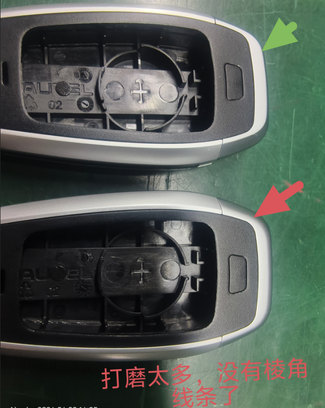
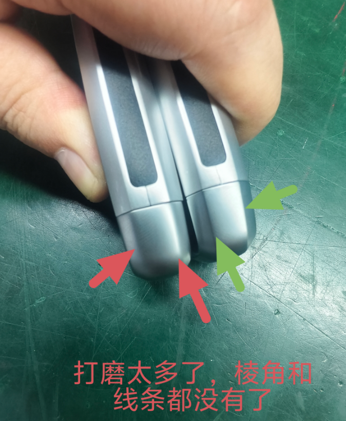
    Excessive polishing removes the original edge definition and makes the end contour visually soft.
    Excessive polishing removes the original edge definition and makes the end contour visually soft.
    A comparison view shows that the over-polished side loses the clear edge and contour line expected after finishing.
    A comparison view shows that the over-polished side loses the clear edge and contour line expected after finishing.
    Rounded edgelost shape definition
    Lost lineweak parting contour
    Dimension losslocal material removal
    Appearance riskbatch inconsistency

    Problem Description

    The defect shown in the production photos is typical over-polishing: the operator removes too much material around the edge and contour area. The original crisp edge, step line or parting-line visual reference becomes rounded and unclear.

    For decorative zinc die cast parts, polishing is not only a surface cleaning process. It directly affects product geometry, edge definition and customer-perceived quality.

    Why Over-Polishing Happens

    CauseWhat HappensQuality Risk
    Casting defect covered by polishingFlow marks, parting flash, dents or carbon marks are removed by grinding instead of solving the upstream causeEdges and lines are consumed while the real casting problem remains
    No limit sampleOperators judge by experience without a clear OK/NG boundaryDifferent workers create different edge shapes
    Wrong abrasive toolCoarse belt, hard wheel or high-speed hand tool removes material too quicklyLocal flat spots, rounded corners and uneven gloss appear
    Uncontrolled pressure and timePolishing force and contact time are not standardizedGood parts become NG parts during finishing
    No protected edge designCritical edge or decorative line has no fixture protectionFeature line disappears after repeated polishing

    How to Judge the Defect

    VisualCheck whether the edge, corner radius, step line and decorative contour are still clear under the same light angle.
    DimensionalMeasure local width, thickness, radius and mating gap before and after polishing to confirm material removal.
    BatchSeparate data by operator, tool, abrasive grade, polishing time and cavity number to locate the main variation source.

    Control Plan

    • Create OK, warning and NG limit samples for edge definition, contour line and surface gloss.
    • Define no-polish or light-polish protected zones around decorative edges, parting lines and assembly references.
    • Replace free-hand heavy grinding with fixture-guided polishing where the edge must be preserved.
    • Use finer abrasive sequence and reduce single-step material removal instead of one aggressive grinding operation.
    • Record abrasive type, tool speed, contact pressure and polishing time for production repeatability.
    • Fix upstream casting causes such as flash, flow mark, shrinkage or carbon mark instead of relying on polishing to hide them.

    Engineering Recommendation

    StageRequired ActionAcceptance Evidence
    Mold trialConfirm whether the edge and parting line are already clean before polishingTrial samples and cavity-separated photos
    Polishing setupLock abrasive grade, fixture, motion direction and maximum polishing timeProcess instruction and operator training record
    First articleCompare with limit sample before batch productionApproved first article photos and measurement data
    Mass productionInspect contour line, edge radius, mating gap and appearance consistencySampling record and defect Pareto

    Conclusion: over-polishing is a process-control failure. The right solution is to reduce upstream defects, protect critical edges, define limit samples and control polishing parameters. Do not use grinding as an unlimited repair method.

    Need help reviewing polishing defects?

    Send photos, drawings, finishing route, limit samples and inspection data. XSD can help separate casting defects, polishing defects and surface-treatment risks.

    Send Defect Data

    质量案例 / 锌合金压铸后处理

    锌合金压铸打磨过度质量问题案例

    说明锌合金压铸件打磨过度如何导致棱角和线条消失,以及如何建立后处理过程控制。

    XSD Precision2026-07-10Zinc Alloy Die CastingPolishing Quality
    这个问题不是简单的外观投诉。锌合金压铸件如果打磨过度,会把设计需要保留的棱角、分型线、轮廓线和局部尺寸一起磨掉,后续装配、电镀或喷涂后会表现为外观不一致、线条不清楚和产品档次下降。
    打磨过度后,端部棱角被磨圆,原本应保留的外观线条变弱或消失。
    打磨过度后,端部棱角被磨圆,原本应保留的外观线条变弱或消失。
    对比样显示:过度打磨的一侧缺少清晰边界和轮廓线,影响装配外观一致性。
    对比样显示:过度打磨的一侧缺少清晰边界和轮廓线,影响装配外观一致性。
    棱角变圆轮廓定义丢失
    线条消失分型边界变弱
    尺寸损失局部材料被磨掉
    外观风险批量一致性差

    问题现象

    图片里的缺陷是典型的打磨过度:操作员在端部、棱边和轮廓线附近去除材料太多,原本应该保留的尖角、台阶线、分型线或装饰线变圆、变钝,甚至完全看不清。

    对装饰类锌合金压铸件来说,打磨不是简单的清理表面。它会直接影响产品几何形状、边界清晰度和客户看到的品质感。

    打磨过度的根因

    原因现场表现质量风险
    用打磨掩盖压铸缺陷流痕、飞边、压伤、积碳印靠打磨处理,而不是解决前端原因棱角和线条被磨掉,真实压铸问题仍然存在
    没有限度样员工凭经验判断,没有清楚的 OK/NG 边界不同员工打出来的棱角和线条不一致
    砂带或工具选择错误砂带太粗、砂轮太硬、手持工具速度过高局部平面、圆角变大、光泽不均
    压力和时间不受控打磨力度、接触时间没有标准良品在后处理过程中被打成不良品
    关键边没有保护装饰线、分型线、装配边没有工装保护重复打磨后特征线消失

    如何判断是否 NG

    外观在同一光线角度下检查棱边、圆角、台阶线和装饰轮廓是否仍然清晰。
    尺寸对比打磨前后的局部宽度、厚度、圆角和装配间隙,确认是否被磨掉材料。
    批量按员工、工具、砂带型号、打磨时间和穴号区分数据,找出主要波动来源。

    过程控制方法

    • 建立 OK、警戒、NG 限度样,明确棱角、轮廓线和表面光泽的接受边界。
    • 对装饰边、分型线、装配基准边设定禁止重磨或轻磨保护区。
    • 关键外观边不要完全自由手打磨,应使用工装限位或导向打磨。
    • 采用更细的砂带顺序,减少单次去除量,不要用一次重磨解决所有问题。
    • 记录砂带型号、工具转速、接触压力和打磨时间,保证批量可重复。
    • 前端压铸的飞边、流痕、缩水、积碳印要从模具和工艺解决,不能长期依赖打磨遮盖。

    工程改善建议

    阶段必须动作验收证据
    试模阶段确认打磨前棱边和分型线是否已经足够干净试模样件和按穴号拍摄的照片
    打磨设定锁定砂带目数、工装、运动方向和最大打磨时间作业指导书和员工培训记录
    首件确认批量前必须和限度样对比首件照片和尺寸数据
    量产检查检查轮廓线、圆角、装配间隙和外观一致性抽检记录和不良 Pareto

    结论:打磨过度不是单纯员工手法问题,而是过程控制失效。正确做法是减少前端压铸缺陷、保护关键棱边、建立限度样并控制打磨参数。打磨不能作为无限制的返修手段。

    需要评估打磨缺陷?

    发送缺陷照片、图纸、后处理路线、限度样和检验数据,XSD 可以协助区分压铸缺陷、打磨缺陷和表面处理风险。

    发送缺陷资料